Dipl.-Ing. Evangelos Kravaritis, Athens, Greece.
Abstract
Traction motors do have several years in operation and for this reason the best practices from the automotive industry could be evaluated for other applications, as electric or hybrid vessels. In the article are analyzed some motor design characteristics that influence the thermal performance of the motor. Furthermore, information is given regarding the cooling systems various traction motors.
Introduction
Motor cooling design is an essential condition for light weight and high torque- density machines, because of the higher current densities in their windings, which can be achieved. A lighter powertrain results in lower overall friction and thus longer range. Moreover, the proper motor thermal design ensures long service life, as the temperature on the winding insulation is a variable that significantly influences the insulation degrading mechanism. The thermal design is coupled with the electromagnetic design. One example of the interdependence of the electromagnetic and the thermal design is the magnet temperature in Permanent Magnet Synchronous Motors, as the increased temperature initially leads to reversible demagnetization and after a certain temperature to partial or complete non reversible demagnetization.
Theory
The motor inherently produces thermal losses which increase the winding temperature and the magnet temperature, which may affect significantly the operation of the motor. In Permanent Magnet Synchronous Motors, which is the majority of the traction motor, copper losses occur in the stator windings due to resistance to current flow. They are proportional to the winding resistance and the square of the current. For each 1°C increase in temperature, the resistance of copper windings increases by about 0.393% of its resistance at 20°C. Copper losses are load depended in comparison with iron losses which are mainly a function of the frequency and the magnetic flux density, i.e. the alternating magnetic fields. Iron losses are composed of hysteresis losses that occur in the laminations and the eddy currents that occur in the laminations and all conductive parts of the motor. At higher frequencies skin effect and proximity losses can increase significantly the losses of the motor. Bearing and windage losses reduce the efficiency especially at higher speeds.
The maximum heat dissipation (W) capacity of the cooling system must be higher than the losses (W) of the motor in order to maintain thermal stability for all ambient temperatures, So, the heat transfers from area with the highest temperature to the area with the lower temperature. Specifically, the copper losses occur in the conductor and the heat path flows through the winding and slot insulation, the stator core and then to the motor housing, where usually the cooling jacket is installed. For this reason, the thermal conductivity of the slot insulation is of critical importance for achieving high power density motors. The copper thermal conductivity is 400 W/m·K but the conductivities of stator lamination and insulation could vary. Specifically, the lamination conductivity could be 28 W/m·K in the radial direction and 8 W/m·K in the axial depending on the material. The insulation material could be down to 0.1 W/m·K. Furthermore, the challenge for electric motors production and assembly is that there is always air between the slot, the insulation paper and the conductor. The air is a poor thermal conductor and thus the heat transfer is deteriorated. For this reason, the thermal simulation might diverge the from experimental test. Manufacturers use thermally conductive impregnation or potting materials, in order to reduce the thermal resistance. Additionally iron losses also increase the temperature of the iron sheet and thus deteriorate the heat transfer.
On the rotor side, the friction losses on the bearings and the eddy currents on the magnets and the rotor are the sources that increase the rotor temperature. Especially eddy currents on the magnets, which conducted heat can increase the magnet temperature and thus lead to partial or permanent demagnetization is widely investigated. It’s very common in traction motors to insert segmented magnets in order to reduce the eddy current path and thus reduce the eddy current losses, as depicted in reference [1].
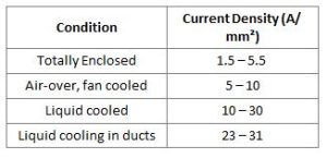
It should be mentioned here that the heat transfer performance of a motor is strongly influenced from the application conditions. For example, traction motors are coupled with a gear and thus the heat from the rotor is conducted to the larger gear mass. For hybrid applications the internal combustion engine might increase the ambient temperature and therefore deteriorate the cooling performance. In case of electric boats someone can suppose that the heat from the rotor will be conducted through the propeller to the water thermal mass. Nevertheless, the impact of the water mass on the stator side is not expected to be significant as the air gap between stator and rotor exhibits high thermal resistance. The more efficient the cooling method the higher the power density, as the heat is dissipated from the critical motor components. Though every application is unique, arbitrarily the current density is used to categorize the maximum electric load as function of the cooling method, as depicted in Table 1.
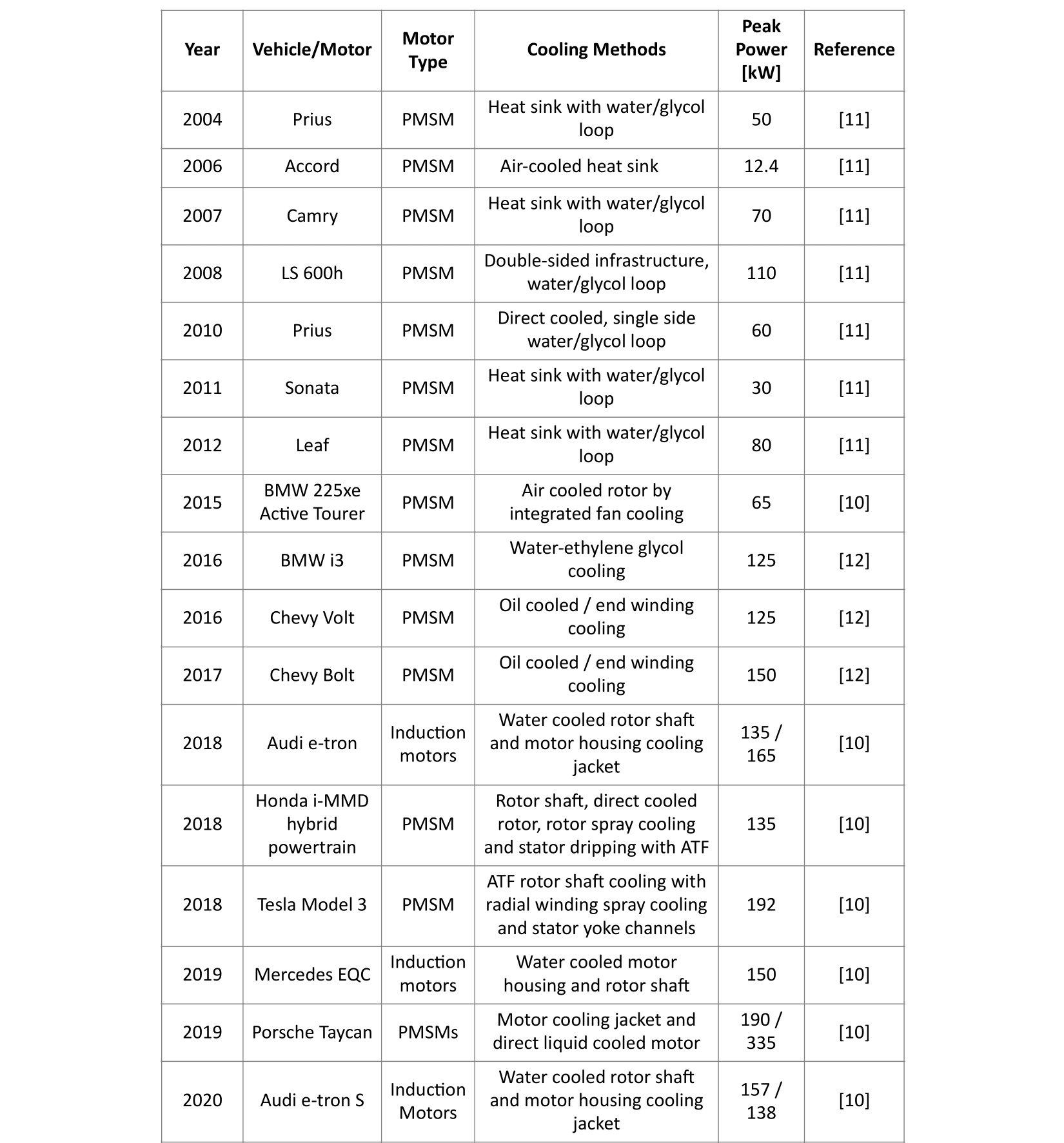
Table 1: PMSM current densities under continuous operation
Cooling systems of traction motors
The power density of traction motors tends to increase, as demonstrated in reference [2]. Apart from the advancements on the cooling system of the electric motor, there are other factors that contribute to the power density increase. The initial traction motor designs were developed for hybrid vehicles, so their duty cycle would not create continuous thermal load as in motors in Battery Electrified Vehicles. Furthermore, the latest powertrains were developed for higher speeds, as the battery voltage tends to increase. Thus, the motor power is produced through the higher speed and not through torque, that requires larger rotor mass. Last but not least the latest motor designs inherit the hairpin winding instead of the traditional round wire windings. Usually, the windings are composed from 4 to 10 rectangular conductors. In this way the heat transfer is conducted much more efficiently in comparison with the traditional round wire, because of the reduction of the surfaces that the heat transfer “confronts” materials with low thermal conductivity, as the winding insulation, the slot insulation and air. A picture of hairpin Vs traditional round winding can be found in reference [3].
In reference [4], it is described the motor development of the last generation of Toyota Prius. Regarding the cooling system the stator and the rotor are actively cooled using the gear lubrication oil. The end windings of the stator are also cooled, as the oil is distributed to the motor and generator sides, and dripped onto the coil ends. The end windings of the stator is the part of the motor that develops the highest temperatures, because the air that surrounds the windings does not conduct the heat effectively.
In references [5] and [6] the motors of Tesla, BYD, Huanwei and Lucid Αir are analyzed and some interesting insights regarding their cooling system can be found. Specifically, Tesla and Lucid air do have micro channels inside the stator lamination as depicted in reference [7] and Figure 1 [8] respectively. The coolant oil (ATF from the gear) flows through the stator and thus dissipates the heat relatively close to the source. After cooling the stator, the oil is used to spray the end windings of the motor in case of Tesla motor. In Tesla the rotor is cooled as well. Further details about the cooling system of Tesla can be found in the reference [9]. In Lucid Air motor the microchannel is close to the slot, as depicted in Figure 1. Then the oil comes in direct contact with the end winding. The proximity to the slots does not influence according to Lucid engineers the flux paths. Analytical description of the Lucid drive can be found in reference [8].
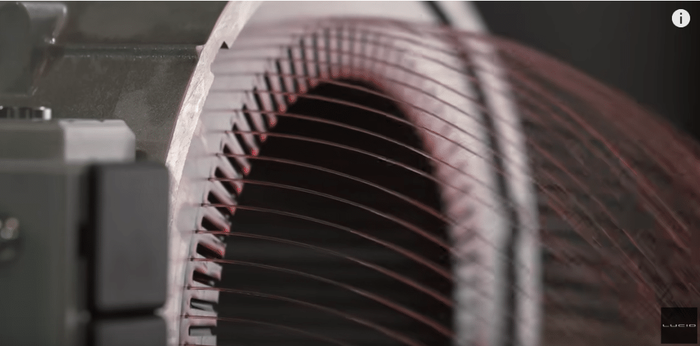
Figure 1. Stator lamina on of Lucid Air Motor [8]
In Table 2 information is collected regarding the cooling systems of traction motors, according to the references [10]-[12].
Table 2: Review of cooling methods of traction motors

The big majority of the first traction motors do have a stator cooling through outer jacket liquid. In this category belongs Nissans LEAF with water/ glycol coolant. In Figure 2 is seen the first generation of Nissan Leaf Stator with the integrated liquid cooling jacket and in Figure 3 is seen cross section of the water jacket. The thermal performance is widely investigated in reference [13].
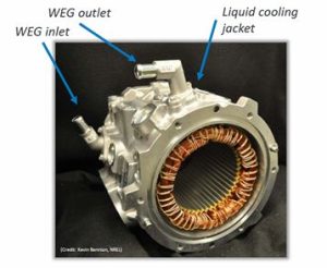
Figure 2 Nissan LEAF Stator water jacket [13]
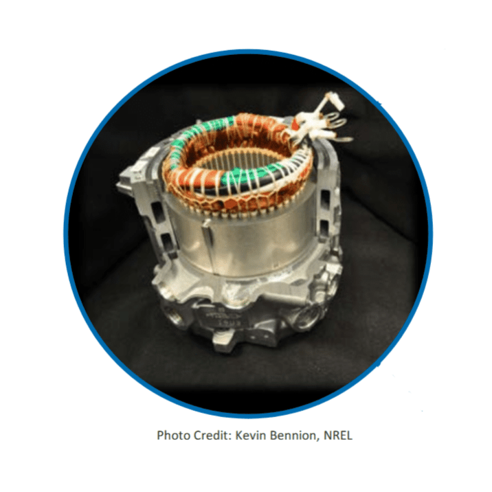 Figure 3. Cross section of Nissan LEAF water jacket [13].
The cooling liquid, usually water glycol, flows in a helical channel around the stator extracting the heat from the stator. Details of the construction of the cooling jacket are given in Figure 4 and 5 from reference [14].
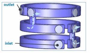
Figure 4. Cooling channels of Nissan Leaf showing the coolant flow path. [14]
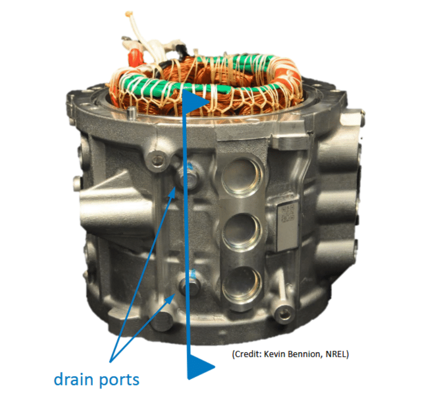
Figure 5. Inlet and outlet view [14]
A difference between the cooling architecture of the latest models of Tesla and Lucid Air and cooling jacket of the first traction motors is that the not conductive oil flows axially through the stator lamination very close to the source of the heat production, ensuring a reduction of the thermal resistance and thus a more efficient heat transfer. Then the coolant oil is used to reduce the temperature of the end windings of the motor. In the majority of the applications the coolant, mostly water with glycol, flows in the jacket helically around the stator. The coolant channel can be axial as well. Nevertheless, the properties of the cooling
channel could influence the coolant pump power. The low temperature of the coolant liquid creates a low temperature in the in the jacket in the periphery of the stator. Thus, the heat from the windings and the laminations mainly is conducted to ambient through the water jacket. In some applications rotor fins are constructed in order the air flow to enhance the heat transfer under the end windings.
The cooling jacket architecture is simple and tested through the years. The tendency of automotive industry is to reduce the motor weight through advanced cooling methods as depicted in Table1. Under this scope Nissan published a new patent in 2021 [15]. As step for further increase of power density is the direct cooling of the conductors, as referred in the literature [16].
Coolant selection
The function of coolants is to absorb and transfer energy with the lowest possible temperature variation. Water ethylene is applied widely in the automotive industry and in traction motors because of the high conductivity, availability and the cost effectiveness. Oil is applied when conductive parts are cooled, i.e. the end windings, to the best knowledge of the writer. Oils used in lubrication do have a wider temperature range than water.
Table 3: Cooling fluids properties – average values @ 0°C to 40°C
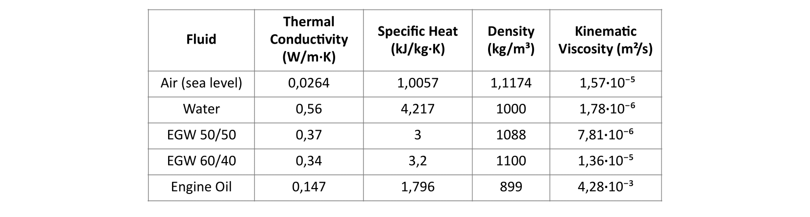
The cooling of motor is a part of the thermal management system that includes the cooling of the inverter and the battery pack. The thermal management system monitors the motor temperature through thermocouples installed usually in end windings, which develop the highest winding temperatures.
Conclusions
An overview of the best practices of motor cooling is presented and analyzed in the article. Apart from the cooling system performance in enhancing the electromagnetic power density, the manufacturing complexity, reliability and maintenance of the cooling architecture, are factors that must be considered in the decision process.
References
[1] A. Krings and C. Monissen, “Review and trends in electric traction motors for battery electric and hybrid vehicles,” in Proc. 2020 Int. Conf. Elect. Machines, 2020, pp. 1807–1813.
[2] C. S. Goli, M. Manjrekar, S. Essakiappan, P. Sahu et N. Shah, «Landscaping and Review of Traction Motors for Electric Vehicle Applications» IEEE Transportation Electrification Conference & Expo, pp. Chicago, IL, USA, 2021.
[3] G. Berardi, S. Nategh, N. Bianchi, and Y. Thioliere, “A comparison between random and hairpin winding in E-mobility applications,” in Proc. 46th Annu. Conf. IEEE Ind. Electron. Soc., Singapore, 2020, pp. 815–820.
[4] S. Sano, T. Yashiro, K. Takizawa, and T. Mizutani, “Development of new motor for compact-class hybrid vehicles,” World Electr. Veh. J., vol. 8, no. 2, pp. 443–449, Jun. 2016
[5] LAM Motor, “Comparison of motor of Tesla, BYD and Huawei,” LAM Motor, Apr. 9, 2023. [Online]. Available: https://lammotor.com/comparison-of-motor-of-tesla-byd-and-huawei/
[Accessed: Jun. 12, 2025]
[6] LAM Motor, “Tesla Model S Plaid vs Lucid Air motor,” LAM Motor, May 2, 2023. [Online].
Available: https://lammotor.com/tesla-model-s-plaid-vs-lucid-air-motor/
[Accessed: Jun. 12, 2025]
[7] Agamloh, E.; von Jouanne, A.; Yokochi, A. An Overview of Electric Machine Trends in Modern Electric Vehicles. Machines 2020, 8,20
[8] Lucid Motors, “Drive Unit: Motor | Tech Talks | Lucid Motors,” YouTube, Apr. 2, 2022. [Online]. Available: https://www.youtube.com/watch?v=U7IHZxNC6hc.
Accessed Jun. 23, 2025.
[9] G. A. Pinkley, D. F. Nelson, W. R. Fong, S. Heines, and E. M. Pearce Jr., “Pressurized and gravity-fed liquid cooling of electric motor,” U.S. Patent 10 439 477 B2, Oct. 8, 2019.
[10] P.O. Gronwald and T. A. Kern, “Traction motor cooling systems: A literature review and comparative study” IEEE Trans. Transport. Electrific., vol. 7, no. 4, pp. 2892–2913, Dec. 2021.
[11] T. Burress, Benchmarking of Competitive Technologies, Oak Ridge National Laboratory, Project ID: APE006, May 15, 2012.
[12] I. Husain, B. Ozpineci, M. S. Islam, E. Gurpinar, G.-J. Su, W. Yu, S. Chowdhury, L. Xue, D. Rahman, and R. Sahu, “Electric drive technology trends, challenges, and opportunities for future electric vehicles,” Proceedings of the IEEE, vol. 109, no. 6, pp. 1039–1059, Jun. 2021
[13] K. S. Bennion, Electric Motor Thermal Management, Tech. Rep. NREL/PR540071208, Project ID: ELT075, National Renewable Energy Laboratory, Golden, CO, presented at the 2018 DOE Vehicle Technologies Office Annual Merit Review and Peer Evaluation Meeting,
Arlington, VA, June 19, 2018
[14] G. Moreno, Thermal Performance Benchmarking, National Renewable Energy Laboratory, presented at the 2015 Annual Merit Review and Peer Evaluation, Washington,
D.C., June 9, 2015, Project ID: EDT070
[15] B. Assaad and E. Negre, “Système de refroidissement à huile d’une machine électrique,” WO Patent 2 021 209 285 A1, Oct. 21, 2021.
[16] E. Nitsche and M. Naderer, “Internally Cooled Hollow Wires Doubling the Power Density of Electric Motors,” ATZelektronik Worldw., vol. 12, no. 3, pp. 42–47, Jun. 2018.